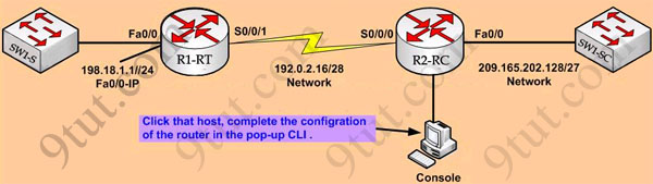
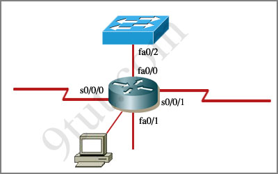
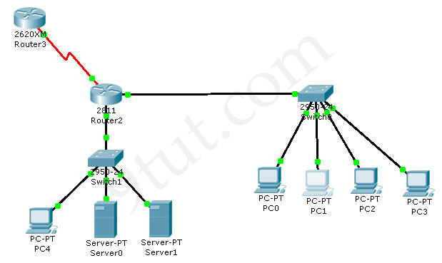
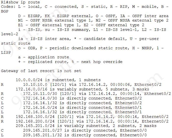
Question
This task requires you to use the CLI of Sw-AC3 to answer five multiple-choice questions. This does not require any configuration.
To answer the multiple-choice questions, click on the numbered boxes in the right panel.
![ccna_vtp_sim_question]()
There are five multiple-choice questions with this task. Be sure to answer all five questions before leaving this item.
Notice: All the images in this VTP LAB are used for demonstration only, you will see slightly different images in the real CCNA exam. You can download this sim to practice here (but notice that this sim is not perfect, only for practicing purpose): http://www.9tut.com/download/9tut.com_CCNA_vtp_sim.pka
If you are not sure about VTP, please read my VTP Tutorial
Note: In this VTP sim, you have to answer 5 questions. After answering the first question, click on the number boxes to move to other questions. If you click “Next” at the first question, you will lose points for 4 remaining questions.
Question 1
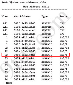
What interface did Sw-AC3 associate with source MAC address 0010.5a0c.ffba ?
a) Fa0/1
b) Fa0/3
c) Fa0/6
d) Fa0/8
e) Fa0/9
f) Fa0/12
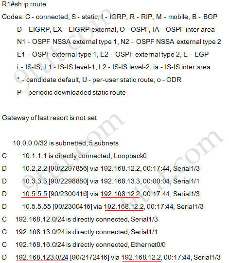
Answer: Fa 0/8
Explanation: to find out which interface associated with a given MAC address, use the show mac-address-table command. It shows the learned MAC addresses and their associated interfaces. After entering this command, you will see a MAC address table like this:
![ccna_vtp_sim_answer_1]()
From this table we can figure out that the MAC address 0010.5a0c.ffba is associated with interface Fa0/8.
Note: There are some reports that the “show mac-address-table” command does not exist in the exam. So in the exam, if you cannot use the “show mac-address-table” command then try using the “show mac address-table” (without “-”) instead.
Question 2
What ports on Sw-AC3 are operating has trunks (choose three)?
a) Fa0/1
b) Fa0/3
c) Fa0/4
d) Fa0/6
e) Fa0/9
f) Fa0/12
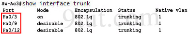
Answer: Fa0/3, Fa0/9 and Fa0/12
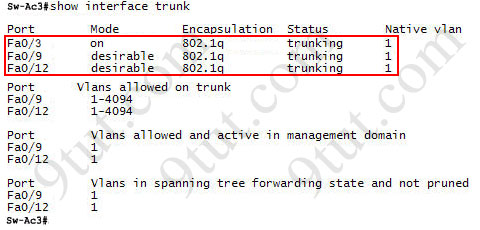
Explanation: Use the show interface trunk command to determine the trunking status of a link and VLAN status. This command lists port, its mode, encapsulation and whether it is trunking. The image below shows how it works:
![ccna_vtp_sim_answer_2]()
(This image is used for demonstration only)
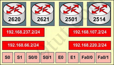
Question 3
What kind of router is VLAN-R1?
a) 1720
b) 1841
c) 2611
d) 2620
Answer: 2620
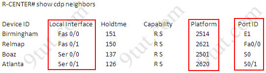
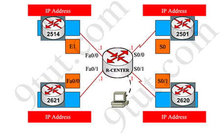
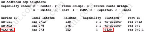
Explanation: VLAN-R1 is the router directly connected to Sw-Ac3 switch, so we can use the show cdp neighbors command to see:
1. Neighbor Device ID : The name of the neighbor device;
2. Local Interface : The interface to which this neighbor is heard
3. Capability: Capability of this neighboring device – R for router, S for switch, H for Host etc.
4. Platform: Which type of device the neighbor is
5. Port ID: The interface of the remote neighbor you receive CDP information
6. Holdtime: Decremental hold time in seconds
Sample output of show cdp neighbors command:
![ccna_vtp_sim_answer_3_2]()
One thing I want to notice you is “Local Intrfce” in the image above refers to the local interface on the device you are running the “show cdp neighbors” command
Question 4
Which switch is the root bridge for VLAN 1?
Answer: Sw-DS1
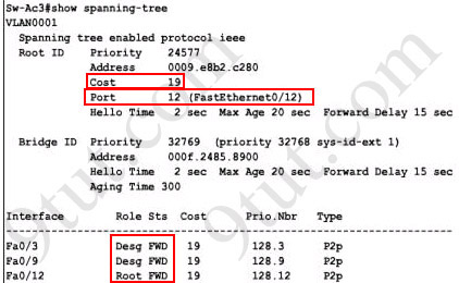
Explanation: First we use the show spanning-tree vlan 1 to view the spanning-tree information of VLAN 1
![ccna_vtp_sim_answer_4]()
From the “Cost 19″, we learn that the root switch is directly connected to the Sw-Ac3 switch over a 100Mbps Ethernet link
Notice that if you see all of the interface roles are Desg (designated) then you can confirm Sw-Ac3 switch is the root bridge for this VLAN (VLAN 1).
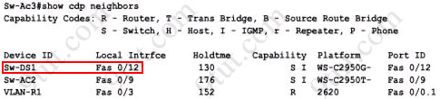
If you see there is at least one Root port in the interface roles then you can confirm Sw-Ac3 is not the root bridge because root bridge does not have root port. In this case, we notice that the root port on Sw-Ac3 switch is FastEthernet0/12, so we have to figure out which switch is associated with this port -> it is the root bridge. You can verify it with the show cdp neighbors command:
![ccna_vtp_sim_answer_4_2]()
The “Local Intrfce” column refers to the interface on the switch running “show cdp neighbors” command. In this case, Sw-DS1 is associated with interface FastEthernet0/12 -> Sw-DS1 is the root bridge
Question 5
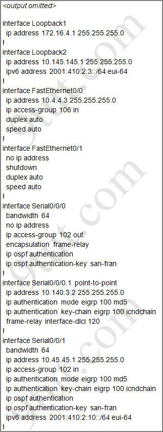
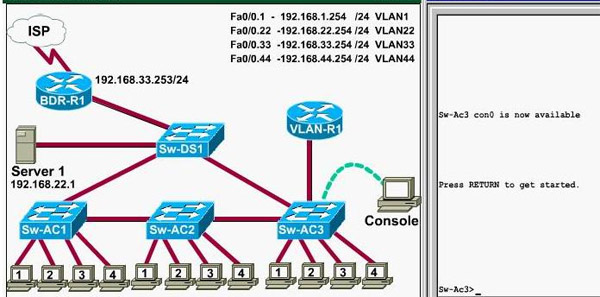
What address should be configured as the default-gateway for the host connected to interface fa 0/4 of SW-Ac3?
Answer: 192.168.44.254
Explanation:
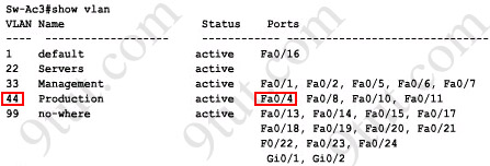
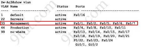
First we have to identify which VLAN interface Fa0/4 belongs to by the show vlan command
![ccna_vtp_sim_answer_4_show_vlan]()
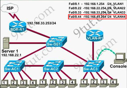
From the exhibit we know that VLAN 44 is configured on router using sub-interface Fa0/0.44 with IP address 192.168.44.254/24
![ccna_vtp_sim_answer_4_part_exhibit]()
Therefore the default gateway of the host should be 192.168.44.254
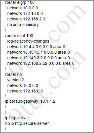
Question 6
From which switch did Sw-Ac3 receive VLAN information ?
Answer: Sw-AC2
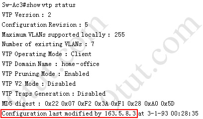
Explanation: to view the VTP configuration information, use the show vtp status command
![ccna_vtp_sim_answer_4_show_vtp_status]()
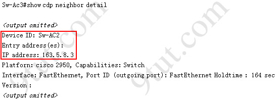
So we knew Sw-Ac3 received VLAN information from 163.5.8.3 (notice:the IP address may be different). Finally we use the show cdp neighbors detail to find out who 163.5.8.3 is:
![ccna_vtp_sim_answer_4_show_cdp_neighbors_detail]()
Question 7
Refer to the exibit, SwX was taken out of the production network for maintenance. It will be reconnected to the Fa 0/16 port of Sw-Ac3. What happens to the network when it is reconnected and a trunk exists between the two switches?
![ccna_vtp_sim_answer_7_new_switch]()
A – All VLANs except the default VLAN will be removed from all switches
B – All existing switches will have the students, admin, faculty, Servers, Management, Production, and no-where VLANs
C – The VLANs Servers, Management, Production and no-where will replace the VLANs on SwX
D – The VLANs Servers, Management, Production and no-where will be removed from existing switches
Answer and Explanation:
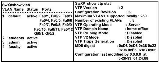
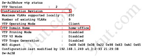
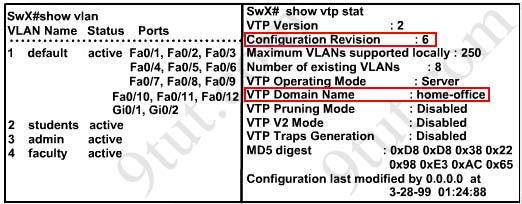
First we should view the VTP configuration of switch Sw-Ac3 by using the show vtp status command on Sw-Ac3
![ccna_vtp_sim_answer_7_new_switch_answer_2]()
Notice that its configuration revision number is 5 and VTP Domain Name is home-office
Next, from the exhibit we know that SwX has a revision number of 6, which is greater than that of Sw-Ac3 switch, and both of them have same VTP Domain Name called “home-office”.
![ccna_vtp_sim_answer_7_new_switch_answer_1]()
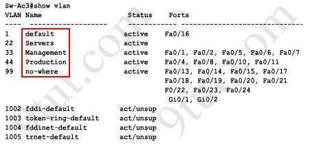
Therefore SwX will replace vlan information on other switches with its own information. We should check vlan information of Sw-Ac3 switch with show vlan command
![ccna_vtp_sim_answer_7_new_switch_answer_3]()
So the correct answer is D – The VLANs Servers, Management, Production and no-where will be removed from existing switches
Please notice that in the real CCNA exam you may see a different configuration revision of Sw-Ac3 or of SwX. In general, which switch has a higher revision number it will become the updater and other switches will overwrite their current databases with the new information received from the updater (provided that they are on the same domain and that switch is not in transparent mode). In particular, if the revision number of SwX is lower than that of Sw-Ac3, the answer should be “C – The VLANs Servers, Management, Production and no-where will replace the VLANs on SwX”.
Also, some recent comments have said that the new switch’s VTP Operating Mode is Server but the answer is still the same.
Note: If a switch is in client mode and has a higher Revision number, it can still update other Server switches (with lower Revision numbers).
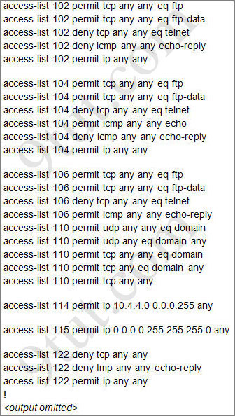
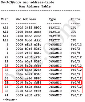
Question 8
Out of which ports will a frame be forwarded that has source mac-address 0010.5a0c.fd86 and destination mac-address 000a.8a47.e612? (Choose three)
A – Fa0/8
B – Fa0/3
C – Fa0/1
D – Fa0/12
Answer: B C D
Explanation:
First we check to see which ports the source mac-address and the destination mac-address belong to by using show mac-address-table command
We notice that the source mac-address 0010.5a0c.fd86 is listed in the table and it belongs to Vlan 33 but we can’t find the destination mac-address 000a.8a47.e612 in this table. In this case, the switch will flood to all ports of Vlan 33 and flood to all the trunk links, except the port it received this frame (port Fa0/6). Therefore from the output above, we can figure out it will flood this frame to Fa0/1, Fa0/3 and Fa0/12.
Please notice that the “show mac-address-table” command just lists information that was learned by the switch, it means that there can be other ports besides Fa0/1, Fa0/3 and Fa0/12 belong to Vlan 33. You can use the show vlan command to see which ports belong to vlan 33
![ccna_vtp_sim_answer_8_2]()
And we found other ports which belong to vlan 33, they are Fa0/2, Fa0/5 and Fa0/7. Our switch will flood the frame to these ports, too.
And we can check which trunk ports will receive this frame by the show interface trunk command
![ccna_vtp_sim_answer_8_3]()
-> Port Fa0/9 will also receive this frame!
Note: Some reports said there is another version of this question. A reader on 9tut commented:
Another question on the VTP SIM was” What will be the destination MAC address of a packet with Source IP address 192.168.44.1 and destination IP address 192.0.2.X (doesn’t really matter what will be the Dest. IP address, since it will be sent to the router).
The answer is simple:
Since the source IP address belongs to VLAN 44, the default gw of the sender is the Router’s Subinterface 192.168.44.254, and this is where the packet will be sent. Thus, you need to perform a ‘show cdp nei’ on the Sw-AC3 in order to find the local FastEthernet port where the router is connected. Then execute a “show mac address-table” (this command was functioning) and find the mac address associated with the previous port. This is the answer.
Question 9
If one of the host connected to Sw-AC3 wants to send something for the ip 190.0.2.5 (or any ip that is not on the same subnet) what will be the destination MAC address?
Answer and Explanation:
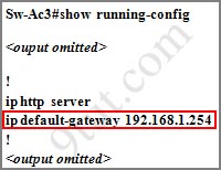
Because the destination address is not on the same subnet with the switch, it will forward the packet to its default gateway. So we have to find out who is the default gateway of this switch by using the show running-config command
![ccna_vtp_sim_answer_9_1]()
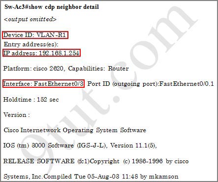
From the output, we notice that its default-gateway is 192.168.1.254. In fact, we can easily guess that its default gateway should be a layer 3 device like a router; and in this case, the VLAN-R1 router. To verify our theory, use the show cdp neighbor detail command and focus on the description of VLAN-R1 router
![ccna_vtp_sim_answer_9_2]()
From this output, we can confirm the switch’s default gateway is VLAN-R1 router (with the IP address of 192.168.1.254). And “the interface: FastEthernet0/3″ tells us that the switch is connected to VLAN-R1 router through Fa0/3 port (Fa0/3 is the port on the switch).
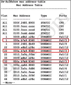
Finally we just need to use the show mac-address-table command to find out which MAC address is associated with this interface
![ccna_vtp_sim_answer_9_3]()
(Notice that in the real CCNA exam the MAC address or port may be different)
And we find out the corresponding MAC address is 000a.b7e9.8360. Although there are some entries of port Fa0/3 with different Vlans but they have the same MAC address
Other lab-sims on this site:
CCNA Access List Sim
CCNA Access List Sim 2
CCNA NAT SIM Question 1
CCNA NAT SIM Question 2
CCNA Frame Relay Sim
CCNA Configuration SIM Question (RIPv2 SIM)
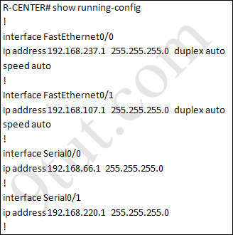
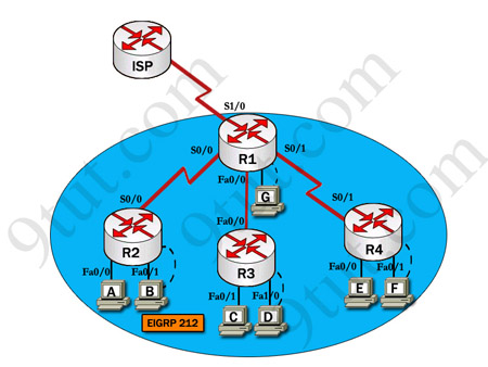
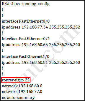
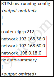
CCNA EIGRP LAB
CCNA Drag and Drop SIM
CCNA Implementation SIM